Comprehensive DBD characterization
- Lionel DUVILLARET
- Apr 27, 2022
- 2 min read
Updated: Oct 24, 2023

DBD and their importance in science and technology
Dielectric-Barrier Discharge (DBD) appear between two electrodes where an insulating dielectric barrier prevents total discharge. DBD can be:
either favorable for the generation of plasma used for surface cleaning, surface preparation for coating, surface sterilization, water treatment, chemical reaction in gases...
or detrimental in High Voltage (HV) devices where Partial Discharges (PD) initiate accelerated aging process which results finally in major failures.
Either to avoid DBD in HV devices or to optimize plasma generation, a comprehensive characterization of DBD is required. DBD characterization can be achieved using a classical PD detector based:
either on conducted emissions generated by the PD and measured as interferences appearing on the signal propagating along a wire, a busbar…
or on radiated emissions generated by the PD and measured as transients received via an UHF antenna.
In both cases, the accurate localization of the PD, at the origin of both conducted and radiated emissions, is impossible because these two classical techniques do not allow near-field measurements of very intense electric (E) field (~ MV/m). At most, they give a rough idea of the average emission of all quasi simultaneous PD.
Prerequisites for a comprehensive DBD characterization
In order to localize a PD and also to distinguish it from other PD occurring at different positions in the device under test, a local electric field probe is required. As any metallic probe would strongly interfere with the E-field to be measured, a local electric field probe must exhibit the following features:
composition of dielectric materials only, all of them presenting an ultra high dielectric strength,
millimeter size and fiber optic probe.
Example of comprehensive DBD characterization

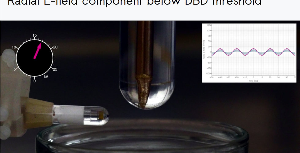
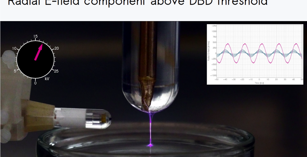
In this example, a test tube filled with pure water and embedding a tapered electrode is connected to a 50 Hz AC high voltage source. Below the test tube a Petri dish filled with pure water is placed on a ground plane and a local electric field probe is positioned for measuring the radial E-field component.
At low voltage the radial E-field strength increases linearly with the applied voltage. Once a certain threshold is passed some DBD appear simultaneously with a dramatic increase of the radial E-field strength. We observe also a phase shift by ~90° of the radial E field component and the appearance of very fast transients on the sinusoidal signal.
Complementary measurements have shown that 3 different regimes can be seen:
a linear regime below 16 kVrms,
a full DBD regime above 18 kVrms,
a transitional regime between them,
Both linear and full DBD regimes can be explained using a simple model of the experimental setup which behavior corresponds to a RC equivalent electrical circuit below 16 kVrms and RR equivalent electrical circuit above 18 kVrms.
Key features of local electric field probe
spatial resolution: < 1 mm
electric field withstand: > 10 MV/m
measurement reproducibility: 0.15 dB
temporal resolution: << 1 ns
measurement inside plasma: perfectly compliant with cold plasma
pressure withstand: from 10-5 up to 7 bar
Please, contact us for more information.


Comments