

Antenna testing in anechoic chamber. Required or not?
- Lionel DUVILLARET
- Nov 24, 2020
- 2 min read
Updated: Jul 11, 2022

Kapteos is introducing a breakthrough in antenna testing with an Artifact-free Near-Field Antenna Test Range (ANFATR).
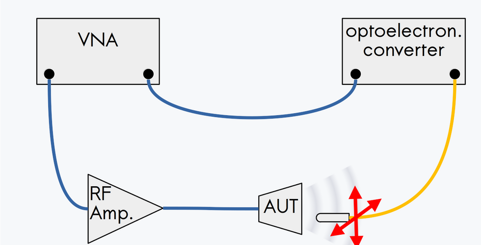
A classical antenna test range is composed of an anechoic chamber with its multi-axis antenna positioner, a vector network analyzer (VNA) and a reference antenna.
Going without an anechoic chamber would lead to a considerable reduction of maintenance cost for the ANFATR, the suppression of the capital assets related to the classical antenna test range specific room, and markedly reduced costs, installation costs and lead times.
This is made possible by using a non-perturbative near field Electric (E) field probe that allows to map the Antenna Under Test (AUT) near field radiation pattern without inducing measurement artifacts.
A non-perturbative near field electric field probe must exhibit:
a low effective permittivity in order not to distort the local electric field,
a metal-free composition for the same reason,
a low loss-tangent composition to be transparent to electromagnetic waves,
a small size to exhibit a high spatial resolution,
a vector behavior to permit its use with a VNA.
a single E field component sensing with high orthogonal components rejection ratio in order to give precise assessment of co- and cross-polarization contributions.
Thanks to a non-perturbative optical technology, Kapteos near field electric field probes eoProbe™ fulfill all these requirements.
How to characterize an antenna in 3 steps

Testing antennas without anechoic chamber is even simpler and faster!
This is achieved in 3 steps.

1st step: VNA calibration
This step is similar to the one carried out with a classical antenna test range.
It consists in making a calibration of the VNA in order to place the reference planes at input port of AUT and at output port of E field probe-related optoelectronic converter.


2nd step: Near field radiation pattern
This step consists in mapping the relative value of the near field through S21 parameter (within λ from AUT aperture) with a sampling lower or equal to λ/5 (λ /10 recommended). For a field mapping on a plane, a standard Cartesian robot makes the job perfectly.
By measuring S11 at the same time, the potential perturbation of both near field electric probe and its holder can be precisely checked and assessed.


3rd step: Far field radiation pattern computation
The last step consists in the numerical forward propagation of the electromagnetic wave from the near-field region to the far-field region. From there, the far field radiation pattern and all its related parameters (AUT gain, polarization, half power beam width, sidelobe level, …) can be easily obtained.
Key features of the near field antenna test range based on Kapteos near field electric field probe
the most compact near field antenna test range ever built: 2 to 5 m² for the whole system
non-perturbative optical technology: S11 <-20 dB for AUT
same probe to cover an ultra wide band: 1 kHz → 65 GHz
ultra high orthogonal E field components rejection ratio: > 50 dB
ultra high spatial resolution: < 1 mm (< λ/5 @ 60 GHz)
high measurement reproducibility: 0.15 dB
ultra compact near field electric field probe: ∅ = 5.5 mm
fully dielectric low permittivity near field electric field probe: εr ~ 3.6
For more information, fell free to contact us.